Ase Vfbga Thickness plays a crucial role in the performance and reliability of electronic devices. This technical aspect, often overlooked, significantly impacts the efficiency and longevity of various applications. This article delves into the intricacies of ase vfbga thickness, exploring its significance, measurement techniques, and industry standards.
What is Ase Vfbga Thickness?
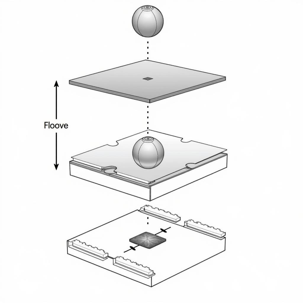
 Ase vfbga package schematic
Ase vfbga (Very Fine-pitch Ball Grid Array) is a type of surface-mount packaging technology widely used for integrated circuits (ICs). The “thickness” in ase vfbga refers to the vertical dimension of the solder balls that connect the IC to the printed circuit board (PCB). These tiny spheres of solder, typically made of a lead-free alloy, provide the electrical and mechanical connection between the IC and the PCB.
Why is Ase Vfbga Thickness Important?
The thickness of ase vfbga balls directly influences the reliability and performance of electronic devices. Here’s why:
- Solder Joint Integrity: Optimal ase vfbga thickness ensures robust solder joints, minimizing the risk of failures due to thermal cycling, vibration, or mechanical shock.
- Signal Integrity: Consistent solder ball thickness contributes to uniform signal transmission, minimizing signal loss and distortion.
- Thermal Management: Proper thickness aids in efficient heat dissipation from the IC to the PCB, preventing overheating and ensuring optimal operating temperatures.
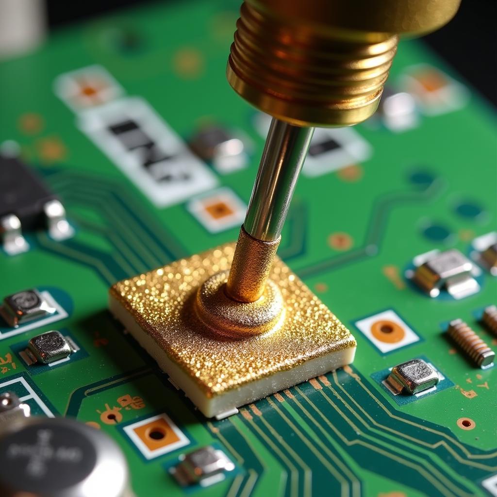
 Cross-section of a solder joint with ideal ase vfbga thickness
Measuring Ase Vfbga Thickness
Accurately measuring ase vfbga thickness is crucial for quality control and ensuring optimal performance. Several methods are employed for this purpose:
- Optical Microscopy: This non-destructive technique uses a high-powered microscope to visually inspect and measure the solder ball height.
- X-ray Inspection: X-ray imaging allows for non-destructive measurement of solder ball thickness even in complex, multi-layered PCBs.
- Laser Profilometry: This method utilizes a laser beam to scan the surface of the solder balls, creating a 3D profile and accurately measuring their height.
Industry Standards and Guidelines
Various industry standards and guidelines define the acceptable range for ase vfbga thickness. These standards ensure compatibility and reliability across different manufacturers and applications. Some key standards include:
- JEDEC (Joint Electron Device Engineering Council)
- IPC (Association Connecting Electronics Industries)
These organizations provide detailed specifications for solder ball dimensions, including thickness, to ensure proper soldering and reliable connections.
Factors Influencing Ase Vfbga Thickness
Several factors can influence the final thickness of ase vfbga balls:
- Solder Paste Deposition: The volume and consistency of solder paste applied during the PCB assembly process directly impact ball formation and thickness.
- Reflow Profile: The temperature and time profile during the reflow soldering process influence solder melting, wetting, and ultimately, ball thickness.
- PCB Design: Factors like pad size, surface finish, and stencil design can affect solder paste deposition and subsequent ball formation.
Troubleshooting Ase Vfbga Thickness Issues
Variations in ase vfbga thickness can lead to soldering defects and reliability issues. Common problems include:
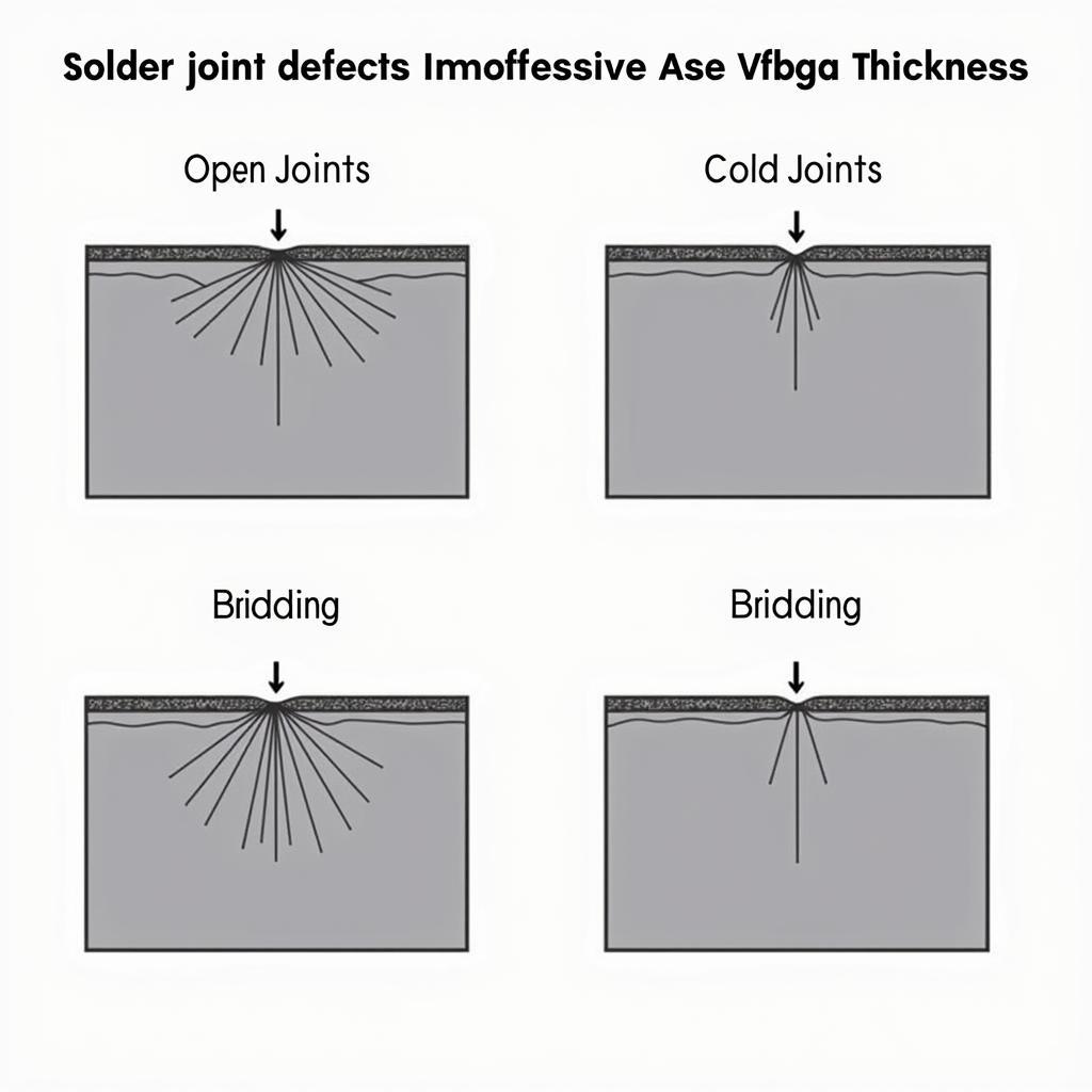
- Insufficient Thickness: This can result in weak solder joints prone to failure under stress.
- Excessive Thickness: Excessively thick solder balls can lead to bridging between adjacent balls, causing short circuits.
Troubleshooting these issues requires careful analysis of the PCB assembly process, including solder paste characteristics, stencil design, and reflow profile optimization.
 Solder joint defects caused by improper ase vfbga thickness
Conclusion
Ase vfbga thickness might seem like a minute detail, but it plays a significant role in the performance and longevity of electronic devices. Understanding its importance, measurement techniques, and industry standards is crucial for ensuring reliable and efficient electronic products. By adhering to best practices and maintaining tight control over the PCB assembly process, manufacturers can ensure optimal ase vfbga thickness for robust and high-performing electronic devices.
FAQ
1. What is the typical ase vfbga thickness range?
The typical ase vfbga thickness range varies depending on the specific IC package and application, but it generally falls between 0.2mm to 0.5mm.
2. What are the consequences of using the wrong ase vfbga thickness?
Using the wrong ase vfbga thickness can lead to solder joint failures, signal integrity issues, and thermal management problems, ultimately impacting the reliability and performance of the electronic device.
3. How can I ensure consistent ase vfbga thickness in my PCB assembly process?
Maintaining consistent ase vfbga thickness requires careful control of solder paste deposition, optimization of the reflow profile, and adherence to industry standards for PCB design and assembly.
4. What are the latest advancements in ase vfbga technology?
Advancements in ase vfbga technology include finer pitch sizes, thinner packages, and improved thermal performance, enabling the development of smaller, more powerful, and more efficient electronic devices.
5. Where can I find more information about ase vfbga standards and guidelines?
Organizations like JEDEC and IPC provide detailed specifications and guidelines for ase vfbga packaging, including solder ball dimensions and assembly processes.
Need further assistance? Contact us:
Phone: 0369020373
Email: aseanmediadirectory@gmail.com
Address: Thôn Ngọc Liễn, Hiệp Hòa, Bắc Giang, Việt Nam
Our customer support team is available 24/7 to answer your queries.

